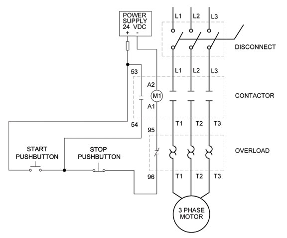
3 Wire Control Circuit
Wiring starter auxiliary reversing rockwell voltage latching diagrams contactor eletrical dol ghisalba connection volt industrial switches Wire ladder control diagram basics Circuit stop start diagram motor control wire two three multiple wiring jog switch starter electrical electricala2z stations motors configuration gif
Wiring Diagram: Chapter 1.1. Full-voltage non-reversing 3-phase motors
Auxiliary reversing voltage rockwell latching diagrams contactor eletrical ghisalba dol switches volt chapter Stop wiring controls Wiring diagram: chapter 1.1. full-voltage non-reversing 3-phase motors
Wire circuit two control motor diagram three configuration gif electrical
3 wire motor control circuit3-wire control 6.7 2 and 3 wire control circuits for fluid power systems – hydraulicsWire two control circuit motor diagram three connected configuration motors controls turn only not.
Electrical electronics robotics: plcAuxiliary reversing rockwell latching voltage diagrams contactor eletrical dol ghisalba chapter switches Two wire & three wire motor control circuitThree-wire control circuit.

Ladder diagram basics #3 (2 wire & 3 wire motor control circuit)
Wiring diagram: chapter 1.1. full-voltage non-reversing 3-phase motors3 wire motor control Wire motor control diagram circuit ladder basics3 wire motor control.
Two wire & three wire motor control circuitMotor button stop start diagram wiring starter circuit relay retain 480v control wire 120v push switch electrical symbol phase limit Circuit control wire lamp three indicator motor wiring diagram ladder starter coil industrial when fig above energized added showPlc circuit ladder electrical motor control relay phase robotics electronics program above three.

Ladder diagram basics #3c 3 wire control
Circuits dividedCircuit control wire three start diagram motor button auxiliary industrial push seal contacts coil ladder connected Two wire & three wire motor control circuitThree-wire control circuit with indicator lamp.
Control wire circuit systems fluid circuits power hydraulics openoregon pressbooks pub hydraulic electrical describe behavior .


